Further observations for group 2 fluorescence features
The overlap between the Raman signals from dehydrated perchlorates and phosphates coupled with low signal-to-noise made distinguishing between these assignments challenging in some cases. The key difference in mineral associations was that in three Máaz fm targets (Montpezat, Bellegarde and Alfalfa), the group 2 fluorescence feature was also associated with possible detections of pyroxene. By contrast, in the Séítah fm, this feature was associated with a possible detection of olivine in at least one point on each target (Extended Data Table 2).
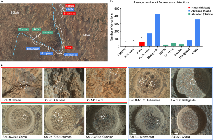
Group 2 fluorescence bands in the natural targets (Máaz fm.) showed a similar shape to those in abraded targets, but the average band position in survey scans was 346.1 ± 2.0 nm, although it may be higher and obscured as it overlaps with the edge of the SHERLOC spectral range. This feature was not correlated to any specific texture. No identifiable Raman bands were detected on these targets, probably due to lower pulses per point (ppp) in the performed scans as well as signal attenuation due to out-of-focus regions and a dust layer; this precluded mineral identification. Signal attenuation aligns with the lower average intensity observed with the group 2 feature on natural targets (188 ± 42 counts) in comparison to dust-free abraded targets.
Potential non-organic luminescence
Luminescence can be caused by non-organic sources as well as organic; however, excitation in the deep UV (less than 250 nm) has the advantage of being in the wavelength range to resonantly excite one- and two-ring aromatics and to avoid most of the interfering luminescence responses from rare earth ions. Nevertheless, the features of the presented dataset (including mineral associations, spatial distribution, frequency of detection, maximum lambda value (lambda max) of the emission bands, and context from previous Mars missions and Martian meteorites) should be compared in the context of each proposed source.
Fluorescence in inorganic minerals, such as feldspars46, can be due to emitters such as rare earth elements (REEs), or lanthanides and other metals within a mineral matrix that can act as activators19. REEs, in most cases, have emissions at wavelengths higher than the SHERLOC spectral range (that is, more than 360 nm)19,48. The most relevant REE to the reported detections is cerium, which can generate emissions within certain minerals in the detection range of SHERLOC. Under 266 nm excitation, Ce3+ in phosphates has been reported to emit roughly 340 nm luminescence49 that resembles some group 2 detections. In the dataset presented here, group 2 fluorescence is not always associated with a Raman identification of a phosphate mineral phase. However, Raman scattering of phosphates is not resonantly enhanced with the SHERLOC DUV laser, so the lack of a Raman detection colocated with 340 nm fluorescence does not preclude Ce3+ in phosphates as the source of the roughly 340 nm emission. The emission spectra of Ce3+ is highly matrix dependent and changes in mineralogy and mineral composition can notably affect the emission profile19. As shown in Fig. 5, the observed fluorescence is associated with a variety of minerals from aqueous processes that include sulfates, phosphates and carbonates, and is similar in position and shape regardless of association. Simple aromatic organic molecules can be preserved in these phases, and therefore are also potential sources for the reported fluorescence. However, it is possible that both organic and inorganic sources, or inorganic sources alone, contribute to the group 2 signals, as REE-bearing phosphates and organics preserved in phosphates have both been reported within Martian meteorites50,51.
In a laboratory study of synthetic ceric sulfate decomposition, strong photoluminescence emissions were reported52. In this study, both laboratory-synthesized and commercial ceric sulfate were heated to 500 °C for 16 h, then observed with a spectrofluorimeter. Ce3+ in both pentahydrated sulfates and anhydrous sulfate yielded double peaked emissions, at 319/339 and 322/339 nm, respectively. This latter observation aligns with other photoluminescence studies53. The closest emissions of cerium within sulfate reported in literature (at 304/327 nm), to the authors’ knowledge, is in a study of synthetic heat-treated anhydrite doped with Ce3+ and observed with cathodoluminescence54. There is an unexplained 12–13 nm difference in emissions of synthetic Ce-doped anhydrite and Ce3+ in natural anhydrite from many locations also measured in this study, indicating that the synthetic sample may not be the most accurate comparison to our dataset. As such, further laboratory analyses on both natural and synthetic cerium-containing sulfate samples are continuing. The lambda max of luminescence emission of cerium in sulfates is expected to shift on the basis of the hydration state of the mineral52. SHERLOC observed sulfates in different states of hydration, for instance on the several observations of the Quartier target, yet the observed fluorescence remained consistent in lambda max. Given the reported emissions of several organic molecules under DUV excitation (Extended Data Fig. 3) in this range, it seems likely that one or more of these molecules may be present in the sulfate minerals. The presence of organics could also possibly explain the Raman detections between roughly 1,300 and 1,650 cm−1. Finally, in the dataset presented here, group 1 was associated with sulfates in all cases; however, many points across targets showed clear Raman peaks of sulfates without the colocated fluorescence signal. This heterogeneity also aligns with the expected patterns of organics distribution. Further examination of the Quartier scans through more detailed analysis and laboratory comparisons is currently underway.
A subset of the signals in group 3 (roughly 281 nm) are also consistent with luminescence associated with defects in irradiated silica caused by oxygen deficiency centres55. However, we do not anticipate that the SHERLOC laser would create such defects, given the high power required to do so. Furthermore, we do not see a clear increase in detections at roughly 281 nm in higher ppp scans in comparison to low ppp, which would be expected if SHERLOC’s laser was inducing such damage. Investigation of other mechanisms (for example, radiation) that would cause localized silica defects that could produce luminescence consistent with group 3 features is continuing.
Future possibilities for Mars sample return
The potential detection of organic molecules by SHERLOC in the abraded targets marked the corresponding cores as high priority for sampling during the crater floor campaign. If these samples are returned to terrestrial laboratories, a more diverse suite of tools can be used to study the samples, including at higher spatial resolution and with much greater specificity and sensitivity. The organic material and mineral relationships can be interpreted within the context of their original locations and stratigraphy, unveiling new insights into organic geochemical cycling on Mars.
SHERLOC spectroscopy general operations
The use of a DUV wavelength may enable more sensitivity to aromatic organic molecules in complex matrices. At 248.6 nm wavelength excitation, a 10 to 1,000-fold increase in Raman scattering is provided by resonance and preresonance with aromatic organic molecules that have a large absorption cross-section. Measured Raman intensities are governed by both their Raman cross-sections and also the number of molecules excited. Transparent minerals with high scattering cross-sections can lead to large intensities whereas relatively few organic molecules in resonance with the SHERLOC laser can lead to similar intensities. Measured fluorescence intensities of mixtures are affected by their quantum yields but also self-absorption. Förster energy transfer can result in the measured intensity of only a single fluorophore even though a mixture of several species exists. Analysis of both fluorescence and Raman data can yield unique insight into mixtures of minerals and organics.
SHERLOC spectroscopy measurements are colocated with 1,648 × 1,200-pixel ACI autofocus full-frame images and placed on the desired target at a 48 mm standoff distance. Activities are constrained by the time of day the laser is operating, optimizing the temperature of the spectrometer CCD to be below −20 °C and reducing contributions from ambient light. Of the 14 instances SHERLOC spectroscopy has run on the surface of Mars to date, there was only one activity that occurred slightly outside this optimal temperature range (the first abraded target, Guillaumes run on sol 161). This temperature constraint to generate valuable science data for SHERLOC means that it is optimal for SHERLOC spectroscopy to be run in the evening, after 20:00 (or early in the morning, but evening is preferred). SHERLOC spectroscopy was conducted on natural samples at midday and abraded samples in the evening, after local sunset, with the abovementioned exception of Guillaumes on sol 161. The robotic arm is capable of placing SHERLOC within 12 mm of a targeted location; SHERLOC’s internal scanning mirror has a positioning error of less than 22 μm at the target. The spectrometer has an estimated uncertainty of ±5 cm−1 (±0.004 nm) in the 700–1,800 cm−1 region, on the basis of the calibration performed on sols 59 and 181. SHERLOC spectroscopy on natural and abraded targets has evolved since the initial natural surface measurement on sol 83. In general, there are two standard suite measurements, with slight modifications where necessary, for SHERLOC spectroscopy and ACI imaging scans: (1) HDR and survey scans, ACI four-image mosaic, ACI 31-image z-stack and (2) detailed scans, which are usually coupled with a survey scan run before the detail scans, for context. In this study, spatial correlations, histograms and average number of detections of fluorescence were conducted using survey scans; mineral-textural-organic correlations were performed using HDR and detailed scans. In the cases of two sols of observation on the same target, the following sols observations were used: Guillaumes 161, Quartier 293 and 304 and Dourbes 257 and 269. Two survey scans were performed on Guillaumes, Dourbes and Quartier. Sol 141 imaging on Foux had an incomplete overlap of WATSON imaging and SHERLOC spectroscopy mapping.
SHERLOC spectroscopy sequences
Natural targets
HDR scans consisted of three sets of 100 spectra, coarse-spaced (780 µm step size), 7 × 7 mm2 scan area, at high ppp (100 ppp for the first two scans, 300 ppp for the final scan). The first natural sample, Nataani, uplinked on sol 83, had 5, 50 and 100 ppp. The survey scan consisted of one scan of 1,296 spectra, 144 µm step size, 5 × 5 mm2 scan area at low ppp; typically, 15 ppp, but 10 ppp and a step size of 200 µm was used for Nataani.
Abraded targets
The first abraded target, Guillaumes, followed the typical HDR scan sequencing, and consisted of three sets of 100 spectra; coarse-spaced (780 µm step size); 7 × 7 mm2 scan area; 100, 100 and 300 ppp followed by a survey scan of 1,296 spectra; 144 µm step size; 5 × 5 mm2 scan area and 15 ppp. In the targets analysed after Guillaumes, HDR scans were changed to two maps of 250 ppp (that is, 250/250) but conserved the total number of laser pulses (500), producing two 50 spectra maps for a total of 100 spectra when combined. The abraded samples also universally used a high laser current (25 A compared to the previous natural surface targets, which were shot at 20 A). When analysing the target, Garde, we had an option to use detailed mode scans for the first time. The initial scan on Garde on sol 207 used the standard suite HDR and survey scans. On sol 208, we did two sets of 50 spectra, 100 µm step size, 1 × 1 mm2 scan area and 500 ppp detailed scans. Although the survey scan was not included in sol 208, it became standard to include for subsequent detail scans (for example, Dourbes on sol 269 and Quartier on sol 304). The scan start position for all HDR and survey scan is at the centre, whereas for the detail scans the scanner starts in the corner or offset position.
SHERLOC imaging operations
The two imaging systems, WATSON and ACI, are mounted atop a rotatable turret on the rover arm and are used during each SHERLOC observation. They are not coboresighted but the resulting images can be registered and overlaid to provide colour and textural information for a single target. WATSON acquires 1,600 × 1,200-pixel colour images of targets of interest from 2.5–40 cm standoff distances to provide broader context within the rock and outcrop. ACI images are always taken before spectroscopy and begin with two 256 × 256-pixel autofocus subframe and full-frame images. Further contextual imaging to support SHERLOC spectroscopy and correlation to images taken by other instruments, spectroscopy operations typically include a four-image ACI mosaic and a 31-image z-stack. The timing and lighting conditions of these products have been adjusted accordingly over the course of the ten targets (and 14 individual sample measurements) that SHERLOC has investigated. Typical operations for LED lighting are to take ACI images with all white LEDs turned on. Dourbes (sol 257) was the first time we had experimented with different lighting conditions on a target. For subsequent standard suite measurements, this update to the LED configuration (different group LEDs on and the use of UV LEDs) became a standard part of the sequences. The scanner is in the home position for the acquisition of the z-stack, which provides surface topographic relief when the in-focus images are assessed on the ground. The scanner is in the mosaic position for acquisition of the mosaic.
Abrasion operations
Each selected target studied after sol 141 was abraded using the rover’s abrasion tool before SHERLOC observation. This tool grinds away the upper layer of rock, cuttings of which are then removed using the gaseous dust removal tool to reveal a fresh surface for analysis14. The resulting abrasion patch is a 45 mm diameter circle with a depth of 8–10 mm.
Spectral data processing
Unsmoothed data without outlier removal were used to determine intensities and band positions. Preliminary spectral data processing was performed using an open-source software package named Loupe developed at the NASA Jet Propulsion Laboratory by K. Uckert. This software enables dark frame subtraction, laser normalization and selection of regions of interest (ROI), as well as the correlation of individual spectra to locations on the ACI image on the basis of the scanning mirror positioning. Exported Loupe data were then further processed using custom Python scripts, Microsoft Excel and Spectragryph52. These were used to perform baseline subtraction, outlier removal, peak detection and median smoothing in a semi-automated manner (the last only for fluorescence data in Fig. 4 and Extended Data Fig. 3). Outliers, generally caused by cosmic rays or charge buildup on the detector, were removed through subtraction and then the remaining data were interpolated across the spectrum. Requirements for fluorescence peak detection included FWHM of at least 100 pixels and more than five times the neighbouring background signal estimated by measurement in Loupe. A 10/1 signal-to-noise ratio was required for quantification, which may have excluded a small number points with actual signal but was deemed a robust criterion for accurate measurement of lambda max and FWHM. Fluorescence spectra used in Figs. 2–4, Extended Data Table 2 and Extended Data Figs. 4 and 5 were smoothed using the Savitzky–Golay algorithm with parameters manually tweaked after comparison to non-processed spectra. This was performed using the SciPy Python package53. This algorithm is known to introduce boundary artefacts45, which can be seen less than 270 nm in several spectra that are not representative of the true data. Fluorescence data were also fitted in Igor64 (Wavemetrics) to allow for measurement of lambda max and FWHM. Bands were fitted using Gaussian or exponentially modified Gaussian functions; baselines were fitted using constant, linear or cubic functions on the basis of visual analysis and chi-squared goodness-of-fit values. For cases in which the fluorescence band was cut off by the edge detector, such as in group 2, the band was always assumed to be symmetric beyond the cut off. For Fig. 5, lambda max and FWHM of each fluorescence spectrum was measured before association to a Raman signal (and possible mineral association) was considered, to maintain objectivity and avoid bias. Requirements for Raman peak detection included FWHM of at least 4 pixels and more than twice the neighbouring (10 pixels) background signal intensity estimated by measurement in Loupe. This width threshold was selected on the basis of the spectral resolution of the instrument (roughly 3–4 pixels)54. FWHM of Raman spectra in Fig. 4 were baselined using the airPLS algorithm55 implemented in Python. Unsmoothed Raman data were fitted using the Multipeak Fit package in Igor64 (Wavemetrics), which enabled peak identification and fitting as well as baseline fitting and chi-squared value approximation. The signal-to-noise ratio for SHERLOC data from the rock surfaces was lower as expected than on calibration targets (Fig. 4); in applicable cases, data from several points were averaged to remove the impact of cosmic rays and improve signal.
Image processing
Image processing on both WATSON and ACI products was performed using a Python script to register several images for a single target to create an overlay. The script uses the OpenCV library built in classes to implement BRISK keypoint detection and a FLANN-based matcher to match keypoints to generate the overlays. ACI ECM products and WATSON ECM or ECZ (roughly 4 to 10 cm standoff) images were used in all cases. Colourized ACI products used for correlating spectral, colour and textural information were generated as previously described16. Small artefacts of bright colours are visible in these colourized images in certain cases.
SHERLOC analogue instrument data
Reference spectra presented were collected on two laboratory instruments, Brassboard (Jet Propulsion Laboratory) and MORIARTI (Mineralogy and Organics Raman Instrumentation for the Analysis of Terrestrial Illumination) (University of Pittsburgh), that are analogues of SHERLOC modified to operate under terrestrial ambient conditions. Brassboard configuration and operations are described in previous literature20. MORIARTI is a custom DUV Raman microscope coupled with several spectrometers to cover the entire Raman and fluorescence (UV and visible light) spectral range. Samples can be illuminated with either a Coherent Industries Innova 300 FreD frequency-doubled Ar+ laser (248.3 nm, roughly 10 mW average power) or a Photon System NeCu laser (248.6 nm, roughly 20 μJ per pulse, 80 Hz). Laser light passes through a 248.6 nm laser clean up filter before being focused onto a turning prism and directed onto the sample as a roughly 120 μm diameter spot. Scattered and emitted light is collected in a 180° backscatter geometry using an f1.25 reflective cassegrain objective and passes through a Semrock 248 nm long-pass filter before entering one of the spectrometers. For Raman, light is dispersed from 250 to 278 nm to a resolution of 9 cm−1 inside an f/6.8 Czerny–Turner spectrograph and focused onto a Princeton Instruments liquid nitrogen cooled Pylon 400B CCD. For UV fluorescence, light is dispersed from 180 to 350 nm to a resolution of 0.5 nm by a custom Ocean Optics QE Pro spectrograph. For visible fluorescence, light is dispersed from 250 to 1,100 nm, to a resolution of 1.5 nm by an Ocean Optics HR4000 spectrograph. The sample can also be illuminated by a halogen white light, in which it is imaged onto a 1.6MP Thorlabs CMOS camera.