Pilot plant design and operation
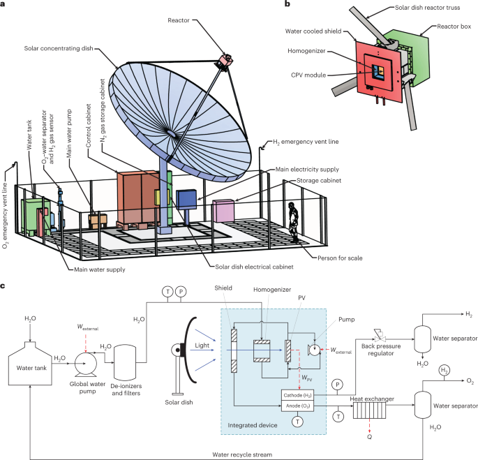
The system is shown in a simplified process and instrumentation diagram in Fig. 1c and is explained further here. A 7 m-diameter dual-axis tracking solar parabolic dish (38.5 m2 collection area) was installed at École Polytechnique Fédérale de Lausanne (EPFL) main campus on a concrete foundation with a covered trench for housing various components and piping. Stainless steel piping and fittings were used for connection of ground-level components, such as upstream components (for example, storage tanks, water pumps, de-ionizers and so on) and downstream components (for example, heat exchangers, water separators, water recycle streams, gas storage tanks and so on). A flexible fluoropolymer-lined tubing was used to make the fluidic connection between the reactor mounted in the focal point of the solar dish and the ground-level components and was routed on a truss of the parabolic dish similar to the electrical and communication cables.
The single continuous feedstock input stream is potable water from the local municipal water supply. The pre-reactor system consists of a water storage tank, a geared water pump, multiple particulate filters and two mixed-bed ion-exchange water deionizers. The water is pumped by the main water pump (this water flow rate is named ‘global’ from here on) via deionizers to the reactor module. The reactor system contains a concentrator triple-junction solar cell module, two 16-cell PEM electrolyser stacks and a small centrifugal pump that was used to recycle (re-circulate) water through the concentrated PV module (this stream is named ‘PV recycle’ from here on). To ensure compatibility of all wetting components with deionized water, as per the the requirements of PEM electrolysis, the wetted surfaces of the concentrated PV module copper heat sink was coated with 50 nm layers of Al 2 O 3 and TiO 2 through atomic layer deposition. All other reactor components (for example, shield, homogenizer, enclosure and so on) were custom made. The goal of the water-cooled flux homogenizer is to convert the approximately Gaussian flux profile of the concentrated sunlight coming from the parabolic concentrator to a rectangular (matching the active area of the PV) homogeneous profile using a kaleidoscope-like design. The homogenizer is constructed from a single hollow block of stainless steel cooled by internal water channels, and the inner faces are covered with highly reflective solar mirrors.
The water is heated as it passes through the light homogenizer, concentrated PV and light shield before it is supplied at an elevated temperature to the EC stack. Accordingly, the integrated device achieves photo-driven thermally assisted water splitting as the waste heat generated from the required forced-convection water cooling of the concentrated PV module raises the water temperature (to 30–90 °C dependant on the water flow rate), which improves the EC performance through improvements in catalysis and membrane performance. The resulting anodic (O 2 + unreacted H 2 O) and cathodic (H 2 + H 2 O by electro-osmotic water drag) streams are transported to ground level.
The product-processing sub-system is comprised of a stainless steel liquid–liquid heat exchanger, custom-made liquid–gas separators (both anodic and cathodic sides) and a back-pressure regulator. The anodic stream is cooled in a liquid–liquid heat exchanger, and then water is removed in the respective liquid–gas separator units and is recycled back to the water storage tank. Hydrogen production pressure is maintained at 1–30 bars by an adjustable back-pressure regulator, and oxygen production is produced at near atmospheric pressure. Finally, the gaseous products are transported to compressed storage ‘quads’ that are connected to EPFL’s mini grid44 or vented to the atmosphere.
The key parameters such as temperature, pressure, conductivity and flow rates are measured at multiple locations, and an in-line flammable gas sensor calibrated for H 2 ensures avoidance of hazardous product crossover (details on gas crossover in Supplementary Note 2). The operating current and voltage of the integrated device was measured with electrical sensors and the temperatures in the reactor by K-type thermocouples. Inlet and outlet temperatures were measured with a PT100 resistance thermometer. The control cabinet houses various data-acquisition boards, relay control boards, power boards, and a computer (running the control software) for controlling and monitoring data collection from various components and sensors. A supervisory control and data-acquisition system was implemented in LabVIEW programming language (National Instruments) to facilitate automated operation and control of the ~30 valves, ~60 sensors, two pumps and so on. The solar dish movement was controlled by a dedicated programmable logic controller.
Commissioning experiments
The electrical performance of the individual PV and EC components are characterized in situ using a 15 kW bi-directional power supply (Supplementary Figs. 6 and 7). The PV performance was also experimentally tested at 1 Sun in the laboratory and at the manufacturer facility at 700 Suns (Supplementary Table 2).
The optical methodology developed in ref. 45 was applied to determine the spatial distribution of the incident solar radiative flux. The radiative flux measurement system consisted of a 275 × 275 mm2 water-cooled custom-made Al 2 O 3 -plasma-coated Lambertian target, a charge-coupled device camera and a graphite-coated radiative flux gauge (repeatability <3%). The need for a geometric transformation of the raw images46 was avoided through coaxial camera positioning with the optical axis of the solar dish. This configuration led to flux map resolution at the target surface of 0.41 mm. Radiative flux maps were taken at varying planes using a custom-built linear stage (positioning precision <1 mm) and were used to assess the optical performance of the system. Further details are provided in Supplementary Methods 1 and Supplementary Figs. 4 and 5.
Integrated experiments and performance metric definitions
A solar irradiance pyranometer was used to continuously monitor the DNI. The startup procedure for the integrated system experiments consist of multiple sequential steps as outlined in Supplementary Fig. 15. The total solar power is defined as Q solar = DNI × A dish . The power of the output fuel is defined as \({Q}_{{{{\rm{fuel}}}}}=\frac{{I}_{{{{\rm{EC}}}}}{N}_{{{{\rm{EC}}}}}{\eta }_\mathrm{F}}{2F}\times {{\Delta }}{E{}_{{{{\rm{H}}}}}}_{{{{\rm{2}}}}}\) where I EC , N EC , η F and F are the current, number of cells in series (= 32), Faradaic efficiency (assumed unity) and the Faraday constant, respectively. Depending on the desired efficiency definition, \({{\Delta }}{E{}_{{{{\rm{H}}}}}}_{{{{\rm{2}}}}}\) is either the reaction enthalpy (\({{\Delta }}{H{}_{{{{\rm{H}}}}}}_{{{{\rm{2}}}}}\) = 286 kJ mol−1) or the Gibbs free energy (\({{\Delta }}{G}_{\mathrm{H}_{2}}\) = 237 kJ mol−1) of water electrolysis under standard ambient conditions (298.15 K, 1 bar). Finally, the power of the output heat is estimated from \({Q}_{{{{\rm{thermal}}}}}={\dot{m}}_{{{{\rm{g}}}}}{C}_\mathrm{p}({T}_{{{{\rm{outlet}}}}}-{T}_{{{{\rm{inlet}}}}})\) where \({\dot{m}}_{{{{\rm{g}}}}}\), C p , T outlet and T inlet are the global mass flow rate of water, heat capacity, system outlet water temperature and system inlet water temperature (at ground level), respectively. The system fuel and thermal efficiency are defined as: η fuel = Q fuel / (Q solar + Q external ) and η thermal = Q thermal /(Q solar + Q external ), respectively. The diagnostic device efficiency is defined as η IPEC = Q fuel /Q PV .
Process simulation
A detailed zero-dimensional steady-state model was formulated to simulate the performance of the integrated system (Supplementary Note 8). For each component (that is, solar dish, homogenizer, PV module, shield, electrolyser and piping), energy and mass balance models were constructed with each component connected by material streams and energetic streams (that is, light, heat and electricity). The PV and EC were simulated via a detailed electrical model, which considered non-homogeneity of light flux at the PV surface. Relevant parameters were obtained from literature or fitted to experimental data for optical, component and integrated system performance (Supplementary Table 8).